Docs › RotoSpider manual › Choose the right shape for a product
Import a CAD file of a complex mold
Describes RotoSpider Desktop 0.8.13 · checked 2026-09-13 D5
When the mold maker has sent a CAD file of the mold with its frame, the Windows desktop app can read it and use the exact shape, including the frame, the clamps and the mounting plate, instead of anything you measure or build. The import takes a few minutes per mold and is done once; the shape then stays with the mold in the workbook.
What you need
- The mold as a STEP file (
.stpor.step), the exchange format every CAD system writes. Other formats are not read. Ask the mold maker for the mold-and-frame assembly as it is bolted to the spider, not the product cavity alone: the frame is what takes the room on the plate. The section getting the file out of your CAD program below says what the file must contain and how to export it. - The Windows desktop app. The Windows installer carries the CAD preparation tools; the macOS and Linux apps can use a shape imported elsewhere (a
Published shape) but cannot import.
Importing
- On the
Mold Datatab, select the mold's row and pressChange Shape, thenImport STEP. - Choose the file. The app reads it and measures how the mold sits, which takes seconds: a few for a small mold, half a minute for a large assembly.
- A dialog headed
Use <file> as <mold>'s shapeopens with what it found and what it will attach:
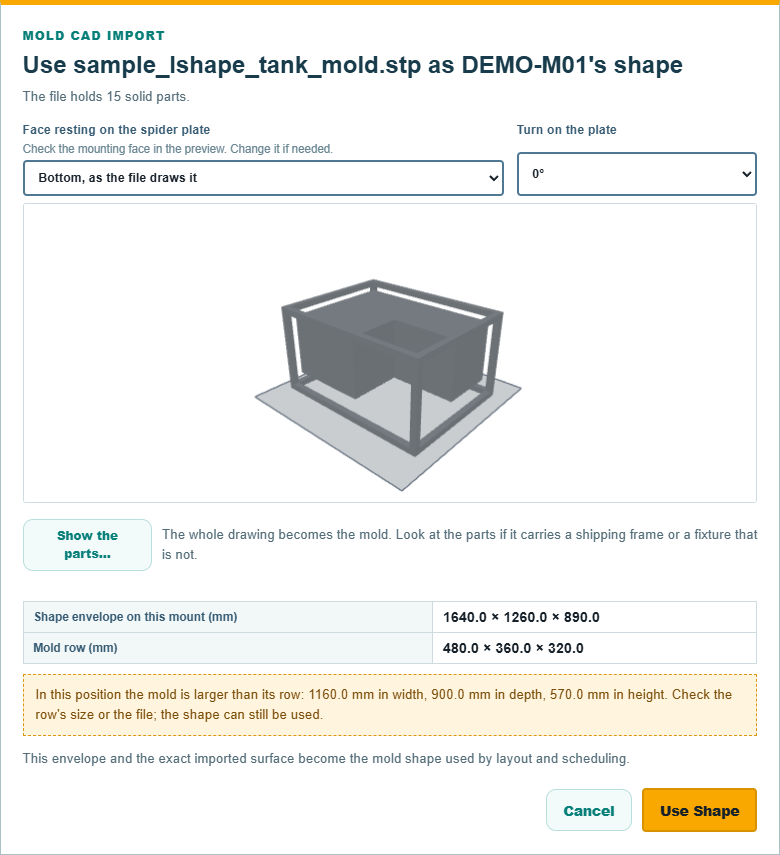
- The first line says how many solid parts the file holds and, when it has them, how many loose sheets lie outside every solid.
- The preview shows the mold resting on a mounting plane.
Face resting on the spider platestarts with the file as drawn when it fits the mold's row dimensions, within 30 mm each way; otherwise the app suggests a face and turn that fit. This is a size-based suggestion: check which face the real frame bolts by. ChooseBottom, as the file draws it,Top, turned over,Front,Back,Left sideorRight side, then useTurn on the platefor quarter turns from0°to270°. The preview follows every change before you pressUse Shape. Shape envelope on this mountshows the outside width, depth and height on the chosen face and turn. It changes as you change them. If the mold is larger than its row dimensions in that position, the dialog warns you and still lets you chooseUse Shape; the measured dimensions replace the row's dimensions when you accept.Show the parts…uses the same preview to show every solid so you can click out the ones that are not the mold: a shipping frame, a machining fixture, a jig. It does not read the file again. Every part is in unless you take it out, and the app refuses to go on if nothing is left. Skip this for a clean file; the whole drawing becomes the mold.-
Sheets lying outside every solid, shown only when the file has loose sheets, is preselected asLeftovers from the drawing — leave them out of the mold. ChoosePart of the mold — keep themonly if you know a real surface of the mold was exported as a sheet. -
Press
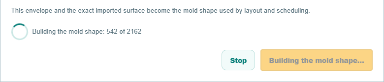
Use Shape. The dialog stays up and reportsReading the parts in the file,Checking the parts in the fileandBuilding the mold shape, with a count of steps done. This is the slow part: about half a minute for a small mold, several minutes for a large assembly.Stopabandons the import; nothing is kept, and the next attempt starts again from the file.
- The row's
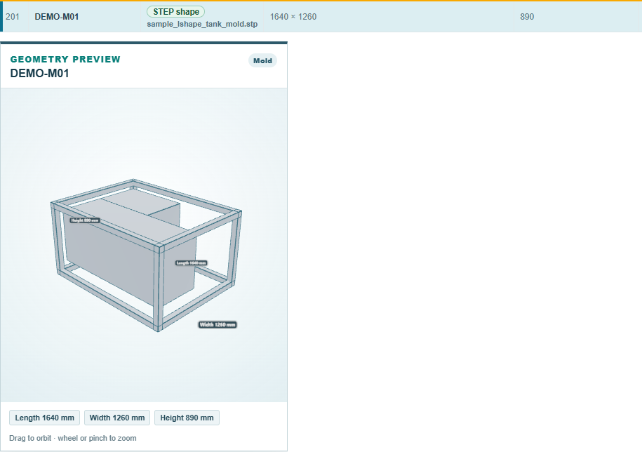
Shapecolumn changes toSTEP shapewith the file's name beneath it, its footprint and height become the measured envelope, read-only, and the preview draws the mold:
The shape is an unsaved edit like any cell change: Save writes it to the workbook after the overwrite question, and closing without saving loses it. Save is unavailable while an import is running.
What the app does with the file
The shape is cut into a coarse solid, at 15 mm normally, finer only when a face of the file will not cut at that size. That is deliberate: a layout needs to know where the mold is to a few centimetres, and every rounding goes outward, so the shape used is never smaller than the mold. The layout tries the imported mold turned in 15-degree steps, and Deeper search in the Machines panel of the layout tab tries every whole degree for imported molds, slower and not always better. Importing the same file twice produces the same shape and changes nothing.
The imported file itself is not kept. What is kept is the shape the app built from it, in the app's own geometry folder on this machine, and the four columns at the end of the mold's workbook row that name it: GeometrySourceKind, ShapeDefinitionId, GeometryAssetId and GeometryAssetRevision. They are written by the app and never typed by hand; a row whose columns do not match a shape on the machine shows no shape until the shape's file is brought over.
Moving a shape to another machine
A shape built from measurements (an L, a wedge, a footprint, a Levels Shape, and the others) can be exported from its row with Export Shape as a .rotoshape file that another machine attaches with Change Shape, Published shape; it stays editable there on a Windows machine. An imported STEP shape is attached on another machine from its .rotogeom file in the geometry folder, read-only. Either way the receiving machine attaches it at once, without a dialog, since the face, the turn and the parts were decided when it was made.
Getting the file out of your CAD program
The import reads what the file holds and never repairs it, so the export decides whether it works. What RotoSpider needs:
- Solid bodies, not surfaces or meshes. Every part of the mold must be a closed solid in the file. Surfaces, sheets and open shells are treated as drawing leftovers and left out; a file with no solid at all is refused. A model drawn as surfaces, or a scanned mesh, has to be made solid in the CAD program first, and a 2D drawing cannot be used at all.
- The whole mold as it bolts to the spider: the two shell halves, the frame, the mounting plate, the clamps that stay on in the oven. One assembly or one multi-body part, as many parts as it takes; the factory files we tried carried several hundred. A shipping frame or a jig is best left out at export; failing that, take it out with
Show the parts…. - Which way up does not matter to the file. Export the model as it is, whichever axis the CAD program calls up and wherever it sits in the file's space. The app suggests a position from the mold row's dimensions, centres the mold on the arm and lifts it to the mounting plane. Check the actual mounting face in the preview and change the face or turn if the suggestion is wrong. The size of a mold cannot tell the app where its frame bolts to the spider.
- Units in the file. STEP carries its own unit, millimetres or inches; the app reads it and asks nothing. Any of the usual STEP flavours is read (AP203, AP214, AP242); the factory files came from Siemens NX as AP214.
- Size. Files of up to 140 MB with 850 bodies have been imported; measuring took under half a minute and building a few minutes. The import stops itself after twenty minutes of building, which no real mold has come near.
Exporting, program by program. The menu names are the programs' own and move between versions; the rule in every case is the same: export the solids, as STEP.
| CAD program | How to export | Watch for |
|---|---|---|
| Siemens NX | File, Export, STEP; AP214 or AP242 | Export the assembly with its solid bodies; the factory files we tried came from here |
| SolidWorks | File, Save As, type STEP AP214; for an assembly save the assembly itself so the parts land in one file | In the options choose solid geometry, not surfaces |
| Autodesk Inventor | File, Save Copy As, STEP | Save the assembly, not a single part |
| Autodesk Fusion 360 | File, Export, STEP | Bodies must be solid bodies |
| PTC Creo | File, Save a Copy, type STEP | Export solids; leave surfaces out |
| CATIA | File, Save As, type stp | |
| AutoCAD (3D) | The STEPOUT command, or File, Export, Other Formats |
Only 3D solids are worth exporting; surfaces and meshes come out as sheets and are left out. AutoCAD LT has no 3D solids, and a 2D drawing cannot be imported |
| Rhino | File, Export Selected, STEP | Only closed polysurfaces become solids; close the model first |
| SketchUp | Not without an add-on; its models are surfaces | Have the mold maker export from their CAD instead |
| FreeCAD | File, Export, STEP |
When a file will not import, or the shape comes out wrong, the cause is usually the export. Of the first four factory files RotoSpider was tried on, three imported as they were; the fourth had a handful of parts, among its largest, whose faces the app could not cut, so they could not be left out either. What helps, in this order: ask the mold maker which CAD program and export settings made the file; ask for a fresh STEP export straight from the native assembly, not a converted or repaired copy; and if that still fails, ask for the model in the CAD program's own format so the export can be done here.
The sample files
The repository ships synthetic sample molds as STEP files for trying the import, under the app's data folder, mold_shapes: an L-shaped tank, a hull, a barrel, a frame with a pocket, and others. None is a real customer's mold.
Comments and questions
The app's rules are our reading of the physics; where your plant knows better, the app changes.