Docs › RotoSpider manual › Set up your factory's data
An offset or L arm, parameter by parameter
Describes RotoSpider Desktop 0.8.13 · checked 2026-09-13 D5
An offset or L arm is a straight arm cranked so that it carries one plate instead of two: the arm tube comes in along its axis of rotation, bends down outside the mold space, and holds the single plate from underneath. Molds mount on the plate's top only, so there is one uninterrupted mounting face instead of two, each half the height. It needs four measurements, a list of the riser stands you own, and an optional load limit.
Two rotations are at work in the arrangement drawn here: the whole set turns about the arm tube's axis, and the plate turns about the axis through its own centre, driven by a shaft inside the hollow arm through a right-angle gear at the plate. "Above", "below" and "top" on this page describe the position drawn; as the arm turns, the whole picture turns with it.
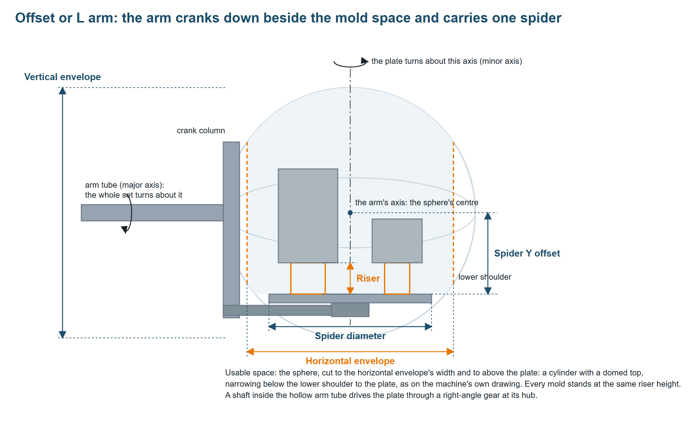
The ball the molds must stay inside is centred where the arm tube's axis of rotation meets the plate's axis of rotation, extended up through the plate's centre; the bend in the arm puts the mounting face below that point, not the centre of the ball. Both rotations keep each corner of a mold at the same distance from that point, so the spherical swing limit applies to an L arm as it does to a straight one. The usable mold space is the part of the ball above the mounting face and within the width the crank column leaves free.
Where this page gives numbers, they are the offset arm built into the web app, which you can open at any time: spider 1800 mm, vertical envelope 2850 mm, spider Y offset 800 mm, horizontal envelope 2400 mm, risers 250 and 500 mm. The trial workbook of the desktop app carries straight arms only.
Spider diameter
What it is. The diameter of the single mounting plate.
How to measure. Across the plate through its centre, or to the tips of the spider arms.
Workbook column OffsetArmSpiderDiaMm; on the tab Spider diameter (mm).
What the layout does with it. Every mold's foot stays inside this circle in plan view; it is also the smallest the ball can be: if the entered vertical envelope is smaller than the plate, the app uses the plate's diameter for the ball. Correct conflicting dimensions against the machine drawing; a bigger ball in the app adds no room in the machine. Too small and molds are refused for lack of spider space; too large and molds are placed past the real plate.
Vertical envelope
What it is. The diameter of the spherical swing limit, centred where the two axes of rotation meet. A mold's height and its reach sideways share this limit; the spider Y offset places the mounting face below its centre.
How to measure. Use the usable spherical swing diameter on the machine maker's mold-swing drawing for this arm, with the clearance allowances the drawing states, and check the limits it gives for the oven, the cooling station and the movement between stations. The diameter is measured through the ball's centre, on the arm tube's axis, not through the plate: the plate is off centre, the ball is not. The height above the plate and the usable horizontal width are separate dimensions, entered below.
Workbook column OffsetArmVertDiaMm; on the tab Rotation / vertical envelope (mm).
What the layout does with it. With the spider Y offset it fixes the ball. Molds must stay inside; a tall mold near the edge is the first to fall out.
When it is wrong. The field must be a positive number; the app refuses to lay out on an arm without it. Too small, and molds are staged with the envelope message. Too large, and the app places molds the oven will not accept.
Further reading. The Association of Rotational Molders' guide to rotational molding machines explains the cranked, single-plate arm beside its Figure 8. Ferry Industries' offset-arm mold-limit drawing shows a spherical swing boundary with a lower mounting face and a separate width limit. Use your own machine maker's drawing for the dimensions.
Spider Y offset
What it is. How far the plate's mounting face sits below the arm's axis of rotation, which is the centre of the ball. The crank puts the plate below the axis; this number is that drop, from the face the molds sit on up to the tube's centre line. It is not the length of the crank column and not the drop of the beam under the plate.
How to measure. From the plate's top face straight up to the centre line of the arm tube, with the arm in the position drawn. On the machines we hold drawings for, this offset is between half and three quarters of the ball's radius, so the plate sits low in the ball and the usable space above it is a tall cylinder with a domed top, narrowing only just above the plate.
Workbook column OffsetArmSpiderYMm; on the tab Dead height / spider Y (mm).
What the layout does with it. It places the plate in the ball. Nothing can go below the plate, so the usable room is the part of the ball above it. The ball is widest at its centre, so the room a mold has depends on where the plate sits: a small offset puts the plate near the widest section, which gives a wide base but less height above the plate; a large offset lowers the plate into the narrowing bottom of the ball, which gives more height but a narrower base, and a riser then lifts a mold back up into the wider part. The height available from the plate to the top of the ball is the ball's radius plus this offset, less what the mold's own footprint takes away at the curve.
When it is wrong. Zero is refused: the plate would sit at the ball's centre. A value as large as the ball's radius puts the plate at the very bottom of the ball, where nothing fits without a riser. Too large a value in general narrows the base every mold stands on; too small a value takes height away from tall molds.
Horizontal envelope
What it is. The usable diameter around the plate's axis of rotation once the crank column beside the plate is allowed for. The machine drawing gives it as the horizontal usable diameter after that trim; the app applies it as an upright cylinder around the plate's centre, the same width all round and at every height. Molds must fit inside both this cylinder and the ball.
How to measure. Take the usable width from the machine maker's mold-swing drawing, with its clearance allowances, and check that it describes the clear diameter around the plate's axis over the whole height the molds will occupy. If you must measure at the machine, check the column and every other obstruction through that height and through the plate's full turn; one gap beside the plate does not establish the whole limit.
Workbook column OffsetArmHorzDiaMm; on the tab Horizontal envelope (mm).
What the layout does with it. It caps how far out a mold may sit at every height. The width available at a height is whichever is smaller there, this cylinder or the ball's section: the ball narrows the space near a low plate as well as near the top, and a riser can lift a mold out of the lower narrowing part; where the cylinder is the smaller one, lifting changes the width nothing.
When it is wrong. The field must be a positive number. Too small, and the layout becomes a narrow tower with molds staged around it. Larger than the ball, and it has no effect: the ball alone limits the layout, right up to where the crank column is.
Risers
What it is. The riser stands (增高架) you own for this arm: welded steel stands that lift every mold off the plate by the same height. Enter every height you have, in millimetres, separated by commas: 400 or 400, 650.
Workbook column OffsetArmRiserHeightMm; on the tab Risers (mm).
What the layout does with it. For each layout the app tries the arm without a riser and with each riser height in the list, and keeps the best result: first the one that places the most molds, then a fully feasible result over a partial one, then the better balance, and if everything still ties, the lowest riser. One height serves the whole layout: every mold stands at that height, and the app does not mix different stand heights on one plate. The chosen height is shown with the result and in the preview.
A riser helps when the lower curve of the ball is what limits a mold: lifted, the mold's foot sits where the ball is wider. Where the horizontal envelope is already the limit at the plate, lifting changes the width nothing; it still raises the mold's top and can improve the balance, and the app judges each height on the result.
When it is wrong. An empty list means only direct mounting is tried. A height that lifts the molds too far into the top of the ball makes some or all of them fail at that height, and the app keeps a lower one. A height in the list you do not own leads to a layout you cannot build; keep the list to the stands on the floor.
Max load
The same as on a straight arm: MaxLoadWeightKg, Max load (kg), empty or 0 for no check. The arm loads molds only up to the limit and the strip says when a request would exceed it.
Checking the numbers
The preview on the Spider / Arm Data tab draws the arm from them:
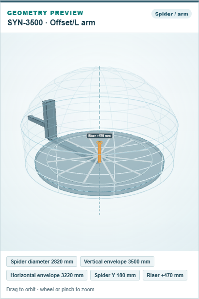
The arm tube should enter at the height of the ball's centre, the crank column should stand outside the usable width, the plate should sit below the centre by the spider Y offset, and the riser should show as a short orange post. The row in the grid carries the same numbers:

Then request one tall mold on the layout tab and read the status strip. If the mold is placed with a riser, the ball and the offset are doing their job. If it is staged, the strip's reason says which limit it broke: an envelope message points at the vertical or horizontal envelope, a spider-space message at the plate, a weight message at the load limit; and a lower riser can succeed where the tallest fails, so compare the heights the app tried.
Comments and questions
The app's rules are our reading of the physics; where your plant knows better, the app changes.